Sharing is Caring

Monday, 15 August 2022
Sunday, 14 October 2018
The manufacturing process of centrifugal casting is a metal casting technique, that uses the forces generated by centripetal acceleration to distribute the molten material in the mold. Centrifugal casting has many applications in manufacturing industry today. The process has several very specific advantages. Cast parts manufactured in industry include various pipes and tubes, such as sewage pipes, gas pipes, and water supply lines, also bushings, rings, the liner for engine cylinders, brake drums, and street lamp posts. The molds used in true centrifugal casting manufacture are round, and are typically made of iron, steel, or graphite. Some sort of refractory lining or sand may be used for the inner surface of the mold.
The Process
It is necessary when manufacturing a cast part by the true centrifugal metal casting process, using some mechanical means, to rotate the mold. When this process is used for industrial manufacture, this is accomplished by the use of rollers. The mold is rotated about its axis at a predetermined speed. Molds for smaller parts may be rotated about a vertical axis. However, most times in true centrifugal casting manufacture the mold will be rotated about a horizontal axis. The effects of gravity on the material during the metal casting process make it particularly necessary to cast longer parts with forces generated from horizontal rather than vertical rotation.Figure:91 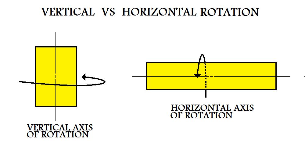 |
The molten material for the cast part is introduced to the mold from an external source, usually by means of some spout. The liquid metal flows down into the mold. Once inside the cavity, the centripetal forces from the spinning mold force the molten material to the outer wall. Molten material for the casting may be poured into a spinning mold or the rotation of the mold may begin after pouring has occurred.
Figure:92 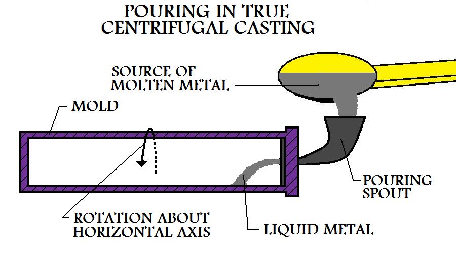 |
The metal casting will harden as the mold continues to rotate.
Figure:93 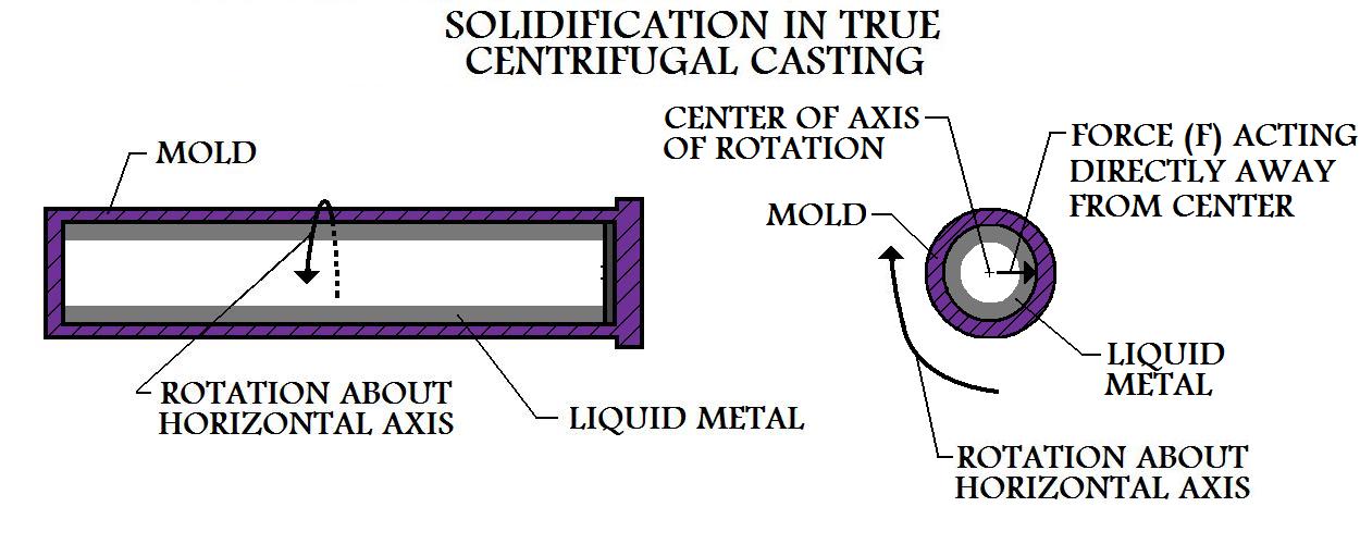 |
It can be seen that this casting process is very well suited for the manufacture of hollow cylindrical tubes. The forces used in this technique guarantee good adhesion of the casting material to the surface of the mold. Thickness of the cast part can be determined by the amount of material poured. The outer surface does not need to be round. Polygonal geometries such as squares and other shapes can be cast. However, due to the nature of the process, the inner surface of a part manufactured by true centrifugal casting must always be round.
During the pouring and solidification phase of true centrifugal casting, the forces at work play a large roll in the properties of castings manufactured by this process. It can be seen that forces will be greater in the regions further away from the center of the axis of rotation. The greater forces towards the rim will cause the regions of the metal casting nearer the outer surface to have a higher density than the sections located nearer the inner surface.
Figure:95 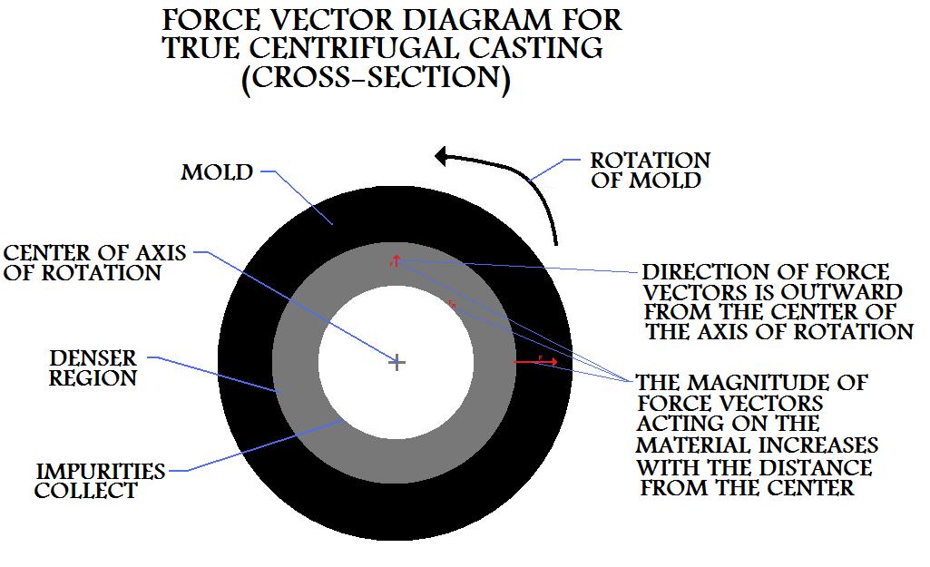 |
Most impurities within the material have a lower density than the metal itself, this causes them to collect in the inner regions of the metal casting, closer to the center of the axis of rotation. These impurities can be removed during the casting operation or they can be machined off later.
Properties And Considerations Of Manufacturing By True Centrifugal Casting
- True centrifugal casting is a great manufacturing process for producing hollow cylindrical parts.
- The metal casting's wall thickness is controlled by the amount of material added during the pouring phase.
- Rotational rate of the mold during the manufacture of the casting must be calculated carefully based on the mold dimensions and the metal being cast.
- If the rotational rate of the mold is too slow, the molten material for the casting will not stay adhered to the surface of the cavity. From the top half of the rotation it will rain metal within the casting cavity as the mold spins.
- This manufacturing operation produces metal cast parts without the need for sprues, risers, or other gating system elements, making this a very efficient industrial metal casting process, in terms of material usage.
- Since large forces press the molten material for the cast part against the mold wall during the manufacturing operation, good surface finish and detail are characteristic of true centrifugal casting.
- Quality castings with good dimensional accuracy can be produced with this process.
- Material of high density and with few impurities is produced in the outer regions of cylindrical parts manufactured by true centrifugal casting.
- Impurities, such as metal inclusions and trapped air, collect in the lower density inner regions of cylindrical parts cast by this process.
- These inner regions can be machined out of the cast part leaving only the dense, more pure material.
- Shrinkage is not a problem when manufacturing by true centrifugal casting, since material from the inner sections will constantly be forced to instantly fill any vacancies that may occur in outer sections during solidification.
- This method can produce very large metal castings. Cylindrical pipes 10 feet in diameter and 50 feet long have been manufactured using this technique.
- With the employment of a sand lining in the mold, it is possible to manufacture castings from high melting point materials such as iron and steels.
- This is a large batch production operation.
- True centrifugal casting is a manufacturing process that is capable of very high rates of productivity.
Hydraulic Brake Systems
Hydraulic operation of brakes has been the universal design for more than 60 years. The complete hydraulic system consists of master cylinder; steel lines, rubber hoses, various pressure-control valves, and brake apply devices at each wheel.

Master Cylinder
The master cylinder is the start of the brake hydraulic system. It actually is a cylindrical pump. The cylinder is closed at one end, and the flexible pushrod extends from the other end. The pushrod moves a pair of in-line pistons that produce the pumping action. The brake pedal lever moves the pushrod this moves the pistons to draw fluid from a reservoir on top of the master cylinder. Piston action forces the fluid under pressure through outlet ports to the brake lines. All master cylinders for vehicles built since 1967 have two pistons and pumping chambers. Motor vehicle safety standards involve this dual-brake system to provide hydraulic system operation in case one wheel brake assembly loses fluid. Because the brake hydraulic system is closed, all the lines and cylinders are full of fluid at all times. The master cylinder develops system pressure the amount of fluid moved is only in less value.

Split Systems
Modern-day vehicles have split brake systems. The pre-1970s vehicle had a single hydraulic system serving all four wheels. A leak anywhere in the system will result in a complete braking failure. The split system is designed to prevent total system failure. This required the use of a dual-piston master cylinder and the inclusion of various valves. A split system is fed by one piston in the master cylinder and feeds two wheel brakes of the vehicle.

There are two types of split systems: diagonal and front/rear. The diagonal system has one system feeding a front-wheel brake and the rear opposing side wheel brake, that is left front and right rear. The second triangle split is to the other wheel brakes. One side or split feeds the rear-wheel brakes and the other feeds the front wheels. Both of these types have advantages and disadvantages, but each prevents complete system failure from a single leak.
Brake Lines and Hoses
The rigid lines or pipes of a brake hydraulic system are made of steel tubing for system safety. Flexible rubber hoses join the wheel brakes to the rigid 7lines on the vehicle body or frame. The front brakes have a rubber hose at each wheel to allow for steering movement. Rear brakes may have different hoses at each wheel or a single hose connected to a line on the body or frame if the vehicle has a rigid rear axle. Brake lines and hoses contain the high-pressure fluid, and the fluid acts like a solid rod to transfer force to the wheel cylinders and caliper pistons.
Wheel Cylinders and Caliper Pistons

Technically, the wheel cylinders of drum brakes and the caliper pistons of disc brakes are “slave” cylinders because they operate in response to the master cylinder. These hydraulic cylinders at the wheels change hydraulic pressure back into mechanical force to apply the brakes. Most late-model systems with drum brakes have a single, two-piston cylinder at each wheel. Hydraulic pressure enters the cylinder between the two pistons and forces them outward to act on the brake shoes. The shoes move outward, the lining contacts the drums to stop the car. The caliper pistons for disc brakes also act in response to hydraulic pressure that enters a fluid chamber in the caliper. Hydraulic pressure in stationary caliper is applied to one or two pistons on each side of the caliper to force the pads against the rotor. Pressure is applied to a single piston in a movable caliper on the inboard side to force the inboard pad against the rotor. Hydraulic pressure is equal in all directions in a closed chamber. This equal pressure creates a reaction force that moves the outboard side of the caliper inward so that both pads grip the rotor.
Wednesday, 21 June 2017
Squeaky steering
Squeaky steering

Whenever a customer complains of noisy steering, the first thing we check is the power steering fluid.
Very often the first sign of fluid loss is an increase in noise as the fluid mixes with air, causing the pump to become noisy.
Not all vehicle owners notice a drip of oil on the road, and if the rack is failing, the oil can still be contained within the rack boots.
This 2001 Ford Focus was in exceptional condition for its age and when the owner noticed the strange noise on turning he bought it along to us.
Checking the fluid level in the steering reservoir, we found it to be almost empty. Putting the Focus up on the ramp for a look underneath, we soon discovered the tell-tale signs of fluid loss and traced the damp trail back to a leaking pressure switch.
Ordering up a new switch, we discovered it came complete with the small section of pipe to which it was connected. At £40, the price was not excessive, and once up and fitted, the leak was cured. After topping up the reservoir, the noise was silenced.
How to fix Whining engine
Whining engine

This picture is of the BMW 330i.
This BMW 330i had developed a whining noise that only stopped when the auxiliary drive belt was removed.
As the belt drives the water pump, along with the alternator, power steering and air condition, as well as running around a couple of idler pulleys, there were quite a few possibilities of where the noise was coming from.
Stripping off the cooling fan and cooling, along with the air filter housing, gave plenty of room to access the problem area.
With the auxiliary belt off, all of the individual pulleys could be spun. Although the water pump was showing slight signs of wear, the bearing appeared to be smooth.
The tension pulley was showing a roughness when spun. The alternator felt smooth when the pulley was spun by hand, but this is not always a guarantee that all is OK as things can change when it’s under load.
In the end, it was discovered that it was indeed the alternator causing the problem when under load. We also took the opportunity to fit a new water pump and tension pulley, both of which needed replacing anyway.
How to change a Fuel Filter of a car
Easiest fuel filter change ever

how to change a fuel filter of a car
When the service parts arrived for this 2009 Audi A6 2.0 TDI, we noted that the fuel filter was a long, slim unit that is normally fitted along the fuel line under the vehicle, either near to the fuel tank or fuel pump.
This is not the case with the A6 diesel. The fuel pump is fitted underneath, near to the engine bay and protected by a plastic undertray, running in line with the front-to-rear fuel lines.
The filter is located under the bonnet and is one of the easiest diesel fuel filters to change – the connecting pipes have spring clips and the filter itself is held in place by the securing bracket using one 10mm nut.
With the ignition off, the filter is easily swapped over and, once in place, it requires no bleeding.
Turning on the ignition for a couple of seconds before attempting to start the engine is sufficient to charge the system with fuel.
Subscribe to:
Comments (Atom)